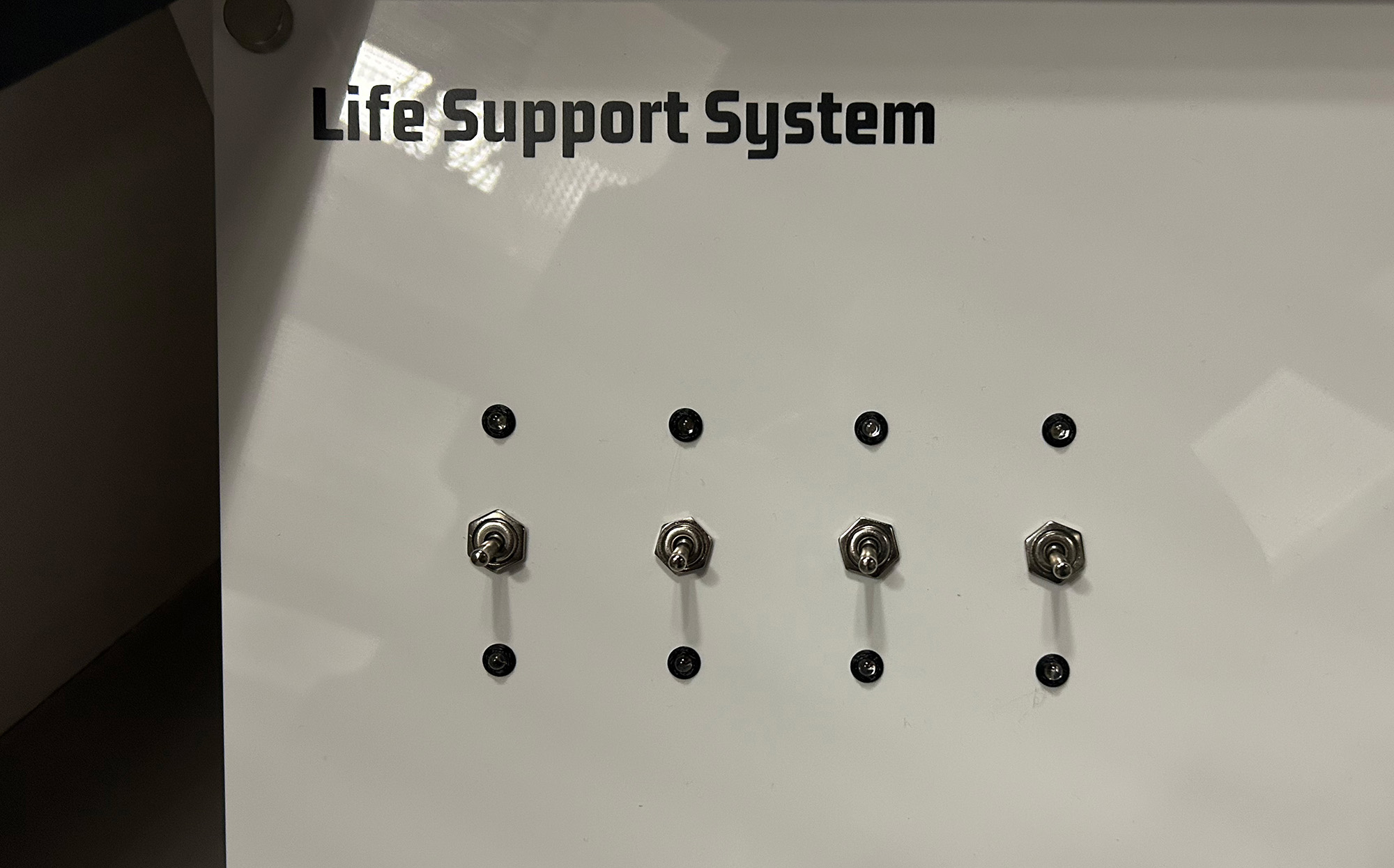
Life Support System
This tutorial creates a spacecraft life support control panel using four toggle switches and LED indicators. This logic puzzle challenges players to activate systems in the correct sequence to restore life support. Each switch affects multiple systems in different patterns, requiring careful observation and logical deduction to solve. Features dual-color LED feedback and serial communication for integration with escape room control systems.
Gameplay Mechanics
The Challenge
Players must toggle switches into ON / OFF positions. Changing each toggle switch, changes the pattern of the red and green LEDs. Players need to discover the correct ON / OFF combination for the four switches.
With 2 positions per switch, there are 16 possible combinations (24), making brute forcing the puzzle a likely option.
How Players Interact
- Observe initial state: All systems show red (offline)
- Test switches: Flip each switch to see which LEDs it affects
- Map relationships: Create a mental model of switch-to-LED connections
- Execute solution: Flip switches in the correct sequence
- Verify success: All green LEDs indicate life support restored
Required Components
Hardware
- 1x Arduino Uno R3
- 4x Toggle switches (SPDT)
- 4x Red LEDs (5mm)
- 4x Green LEDs (5mm)
- 8x 220Ω resistors (for LEDs)
- Jumper wires
- Breadboard
Software Requirements
- Arduino IDE (1.8.0 or later)
Wiring Diagram
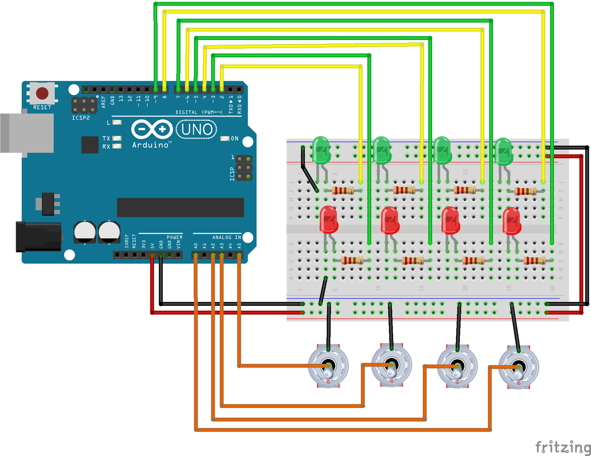
Switch 1
- Switch Common → A5
- Switch Terminal A → GND
- Switch Terminal B → Internal pull-up enabled
- Green LED → Pin 2
- Red LED → Pin 3
Switch 2
- Switch Common → A3
- Switch Terminal A → GND
- Switch Terminal B → Internal pull-up enabled
- Green LED → Pin 4
- Red LED → Pin 5
Switch 3
- Switch Common → A2
- Switch Terminal A → GND
- Switch Terminal B → Internal pull-up enabled
- Green LED → Pin 6
- Red LED → Pin 7
Switch 4
- Switch Common → A20
- Switch Terminal A → GND
- Switch Terminal B → Internal pull-up enabled
- Green LED → Pin 8
- Red LED → Pin 9
LED Configuration
- All LED anodes → through 220Ω to pins
- All LED cathodes → GND
Serial Communication
- Used for debugging
- Reset command: "RESETQ"
- JSON output sent to Escape Room server
The Code
1Define Constants and Variables
Set up the pin assignments and state tracking variables:
const String shortName = "LIFE";

// SWITCHES AND LEDs
// Switch 1
const int BTN1 = A5;
const int GRN1 = 2;
const int RED1 = 3;
int RED1_state = 1;  // Start with red ON (system offline)
int GRN1_state = 0;  // Start with green OFF
int btn_1_state = 0;
int btn_1_old = 0;

// Switch 2
const int BTN2 = A3;
const int GRN2 = 4;
const int RED2 = 5;
int RED2_state = 1;
int GRN2_state = 0;
int btn_2_state = 0;
int btn_2_old = 0;

// Switch 3
const int BTN1 = A2;
const int GRN1 = 6;
const int RED1 = 7;
int RED1_state = 1;
int GRN1_state = 0;
int btn_1_state = 0;
int btn_1_old = 0;

// Switch 4
const int BTN2 = A0;
const int GRN2 = 8;
const int RED2 = 9;
int RED2_state = 1;
int GRN2_state = 0;
int btn_2_state = 0;
int btn_2_old = 0;

int LED_setup = 0;        // Initialization flag
int victoryAchieved = 0;  // Track if puzzle is solved
Variable organization:
Button pins: Using analog pins as digital inputs (A0, A2, A3, A5) for the switches.
LED pairs: Each system has a red LED (offline) and green LED (online) for clear status indication.
State tracking: Separate variables track current and previous button states for edge detection.
Victory flag: Prevents sending redundant "unsolved" messages before first solution.
2Setup Function
Initialize all pins and serial communication:
void setup() {
    // Configure all button pins with internal pull-up resistors
    pinMode(BTN1, INPUT_PULLUP);
    pinMode(RED1, OUTPUT);
    pinMode(GRN1, OUTPUT);

    pinMode(BTN2, INPUT_PULLUP);
    pinMode(RED2, OUTPUT);
    pinMode(GRN2, OUTPUT);

    pinMode(BTN3, INPUT_PULLUP);
    pinMode(RED3, OUTPUT);
    pinMode(GRN3, OUTPUT);

    pinMode(BTN4, INPUT_PULLUP);
    pinMode(RED4, OUTPUT);
    pinMode(GRN4, OUTPUT);

    Serial.begin(9600);
}
Setup explained:
INPUT_PULLUP: Enables internal pull-up resistors, eliminating the need for external resistors.
LED outputs: All 8 LEDs configured as outputs for direct digital control.
Serial communication: 9600 baud rate for compatibility with most serial monitors and systems.
3Switch Logic Implementation
Each switch affects different combinations of LEDs, creating the puzzle logic:
Switch 1 - Toggles LED 1 Only
/* SWITCH 1 TOGGLE FUNCTION */
if(btn_1_state != btn_1_old){
    // Toggle LED 1
    RED1_state = !RED1_state;
    GRN1_state = !GRN1_state;
    digitalWrite(GRN1, GRN1_state);
    digitalWrite(RED1, RED1_state);
    btn_1_old = btn_1_state;

    sendUpdate(shortName, "UPDATE", btn_1_state, btn_2_state,
               btn_3_state, btn_4_state, "1", "false");
    checkVictory(GRN1_state, GRN2_state, GRN3_state, GRN4_state);
}
Switch 2 - Toggles LEDs 1 and 3
/* SWITCH 2 TOGGLE FUNCTION */
if(btn_2_state != btn_2_old){
    // Toggle LED 1
    RED1_state = !RED1_state;
    GRN1_state = !GRN1_state;
    digitalWrite(GRN1, GRN1_state);
    digitalWrite(RED1, RED1_state);

    // Toggle LED 3
    RED3_state = !RED3_state;
    GRN3_state = !GRN3_state;
    digitalWrite(GRN3, GRN3_state);
    digitalWrite(RED3, RED3_state);
    btn_2_old = btn_2_state;
}
Switch 3 - Toggles LEDs 2 and 3
/* SWITCH 3 TOGGLE FUNCTION */
if(btn_3_state != btn_3_old){
    // Toggle LED 2
    RED2_state = !RED2_state;
    GRN2_state = !GRN2_state;
    digitalWrite(GRN2, GRN2_state);
    digitalWrite(RED2, RED2_state);

    // Toggle LED 3
    RED3_state = !RED3_state;
    GRN3_state = !GRN3_state;
    digitalWrite(GRN3, GRN3_state);
    digitalWrite(RED3, RED3_state);
}
Switch 4 - Toggles LEDs 1 and 4
/* SWITCH 4 TOGGLE FUNCTION */
if(btn_4_state != btn_4_old){
    // Toggle LED 1
    RED1_state = !RED1_state;
    GRN1_state = !GRN1_state;
    digitalWrite(GRN1, GRN1_state);
    digitalWrite(RED1, RED1_state);

    // Toggle LED 4
    RED4_state = !RED4_state;
    GRN4_state = !GRN4_state;
    digitalWrite(GRN4, GRN4_state);
    digitalWrite(RED4, RED4_state);
}4Victory Checking and Reset
Monitor for success condition and handle remote reset commands:
// Function to check for victory condition
void checkVictory(int btn1, int btn2, int btn3, int btn4){
    if(btn1 == 1 && btn2 == 1 && btn3 == 1 && btn4 == 1){
        // All systems online - puzzle solved!
        Serial.println("{\"shortName\":\"" + shortName +
                         "\",\"type\":\"SOLVE\",\"solved\":true}");
        victoryAchieved = 1;
    } else if(victoryAchieved == 1){
        // Was solved but now isn't - send unsolved message
        Serial.println("{\"shortName\":\"" + shortName +
                         "\",\"type\":\"SOLVE\",\"solved\":false}");
    }
}

// Programmatic reset function
void(* resetFunc) (void) = 0; // Reset function at address 0

// Check for reset command in main loop
if(victoryAchieved == 1){
    if(Serial.available()){
        thisChar = Serial.read();
        if(thisChar != 'Q'){
            incomingString += thisChar;
        } else {
            if(incomingString == "RESET"){
                resetFunc(); // Call reset function
            }
        }
    }
}
Victory and reset logic:
Success condition: All four green LEDs must be on (all systems online).
JSON output: Sends structured messages for integration with escape room control systems.
Software reset: Responds to "RESETQ" command to restart the puzzle remotely.
State tracking: Only sends "unsolved" message if puzzle was previously solved.
5Main Loop and LED Initialization
The main loop handles initialization and continuous monitoring:
void loop() {
    // Set initial LED values: Red on, Green off
    if (LED_setup == 0) {
        digitalWrite(RED1, HIGH);
        digitalWrite(GRN1, LOW);
        digitalWrite(RED2, HIGH);
        digitalWrite(GRN2, LOW);
        digitalWrite(RED3, HIGH);
        digitalWrite(GRN3, LOW);
        digitalWrite(RED4, HIGH);
        digitalWrite(GRN4, LOW);
        LED_setup = 1;

        // Send initialization message
        sendUpdate(shortName, "INITIATION", btn_1_state, btn_2_state,
                   btn_3_state, btn_4_state, "-", "false");
    }

    // Read button states
    btn_1_state = digitalRead(BTN1);
    btn_2_state = digitalRead(BTN2);
    btn_3_state = digitalRead(BTN3);
    btn_4_state = digitalRead(BTN4);

    // Switch logic checks here...

    delay(200); // Debounce delay
}
Testing Your Life Support System
1Understanding the Solution
The puzzle solution requires all four green LEDs to be on. Based on the switch logic:
Solution Analysis:
Starting from all LEDs red (offline), the optimal sequence is:
- Flip Switch 3 - HIGH: Turns on LEDs 2 and 3 (green)
- Flip Switch 4 - HIGH: Turns on LEDs 1 and 4 (green)
Result: All four systems online with just two switch flips!
Why this works:
- Switch 3 affects LEDs 2 & 3 - both start red, so both turn green
- Switch 4 affects LEDs 1 & 4 - both are still red, so both turn green
- No LED is toggled twice, so all end up green
2Hardware Test Sketch
Test your wiring with this simple verification sketch:
void setup() {
    Serial.begin(9600);

    // Configure all pins
    for(int pin = 2; pin <= 9; pin++) {
        pinMode(pin, OUTPUT);
    }

    pinMode(A0, INPUT_PULLUP);
    pinMode(A2, INPUT_PULLUP);
    pinMode(A3, INPUT_PULLUP);
    pinMode(A5, INPUT_PULLUP);

    // Test all LEDs
    Serial.println("Testing all LEDs...");
    for(int pin = 2; pin <= 9; pin++) {
        digitalWrite(pin, HIGH);
        delay(200);
        digitalWrite(pin, LOW);
    }
}

void loop() {
    // Print button states
    Serial.print("Buttons: ");
    Serial.print(digitalRead(A5));
    Serial.print(" ");
    Serial.print(digitalRead(A3));
    Serial.print(" ");
    Serial.print(digitalRead(A2));
    Serial.print(" ");
    Serial.println(digitalRead(A0));
    delay(500);
}3Troubleshooting Common Issues
LED Problems
- Check LED polarity (long leg = anode)
- Verify 220Ω resistors are connected
- Test LEDs with simple blink sketch
- Ensure common ground connections
- Try swapping red/green if colors reversed
Switch Issues
- Verify pull-up resistors are enabled
- Ensure switches connect to ground
- Try external 10kΩ pull-ups if needed
Logic Not Working
- Verify switch-to-LED mapping
- Check state variables are updating
- Add Serial.print debugging
- Ensure 200ms debounce is sufficient
- Test each switch individually first
Possible Enhancements
Timer System
Add a countdown timer that triggers an alarm if life support isn't restored quickly enough, increasing pressure on players.
LCD Display
Connect an I2C LCD and add system names and status messages like "OXYGEN CRITICAL" or "TEMPERATURE STABLE".
Randomized Logic
Implement different switch-to-LED mappings that change each game, preventing memorization of solutions.
Progressive Difficulty
Start with 3 systems and add the 4th after initial success, or change the logic patterns between rounds.
Status Display
Add a 7-segment display showing the number of systems online (0-4) for quick status reference.
Get in touch!
We are currently looking for educators and students to collaborate with on future projects.
Get in Touch!
hello@escapehumber.ca