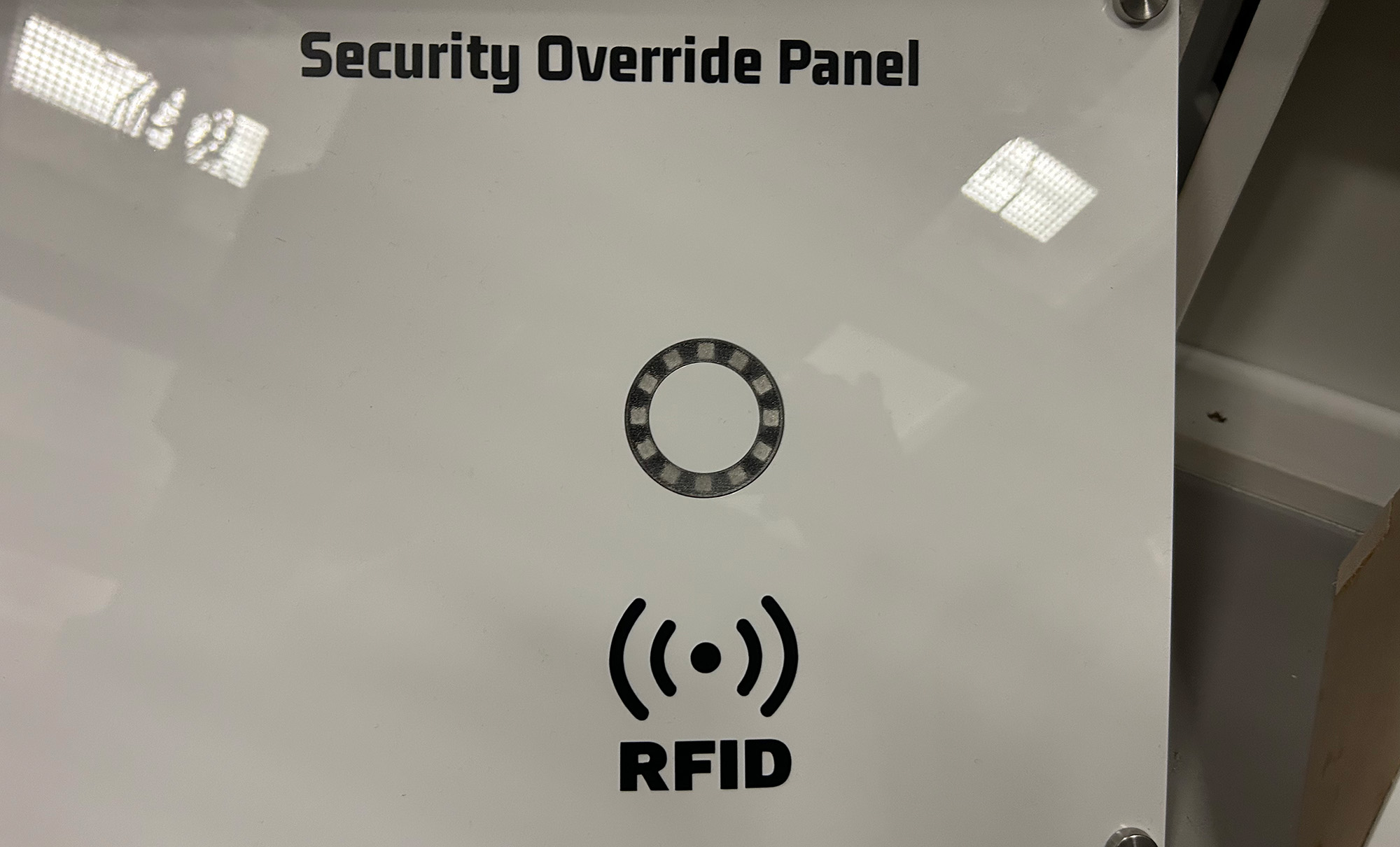
Security Override Panel
This tutorial creates an RFID-based security system with visual LED feedback. The system validates RFID cards and provides different LED animations based on the authentication result.
Gameplay Mechanics
The Challenge
Players must find the correct keycard to activate the security override. The keycard is hidden inside the escape room. This puzzle is meant to be the first task the players must complete in the escape room. As such, it is meant to be an easy introduction.
The difficulty of this puzzle can be increased by adding multiple keycards, and increasing the difficulty of where the keycard is hidden.
How Players Interact
- Observe current values: LED ring is in a circular red pattern
- Tap keycard: Players tap a keycard to an RFID reader
- Read result: LED ring shows Invalid card (red flash) or Success animation (green cascade). LED ring transitions to solved/idle state, after success animation.
Required Components
Hardware
- 1x Arduino Uno R3
- 1x MFRC522 RFID Reader Module
- 1x NeoPixel Ring (12 LEDs)
- 2-3x RFID Cards/Tags (13.56 MHz)
- Jumper wires
- Breadboard (optional)
Software Requirements
- Arduino IDE (1.8.0 or later)
- MFRC522 Library by GithubCommunity
- Adafruit NeoPixel Library
- SPI Library (built-in)
Wiring Diagram
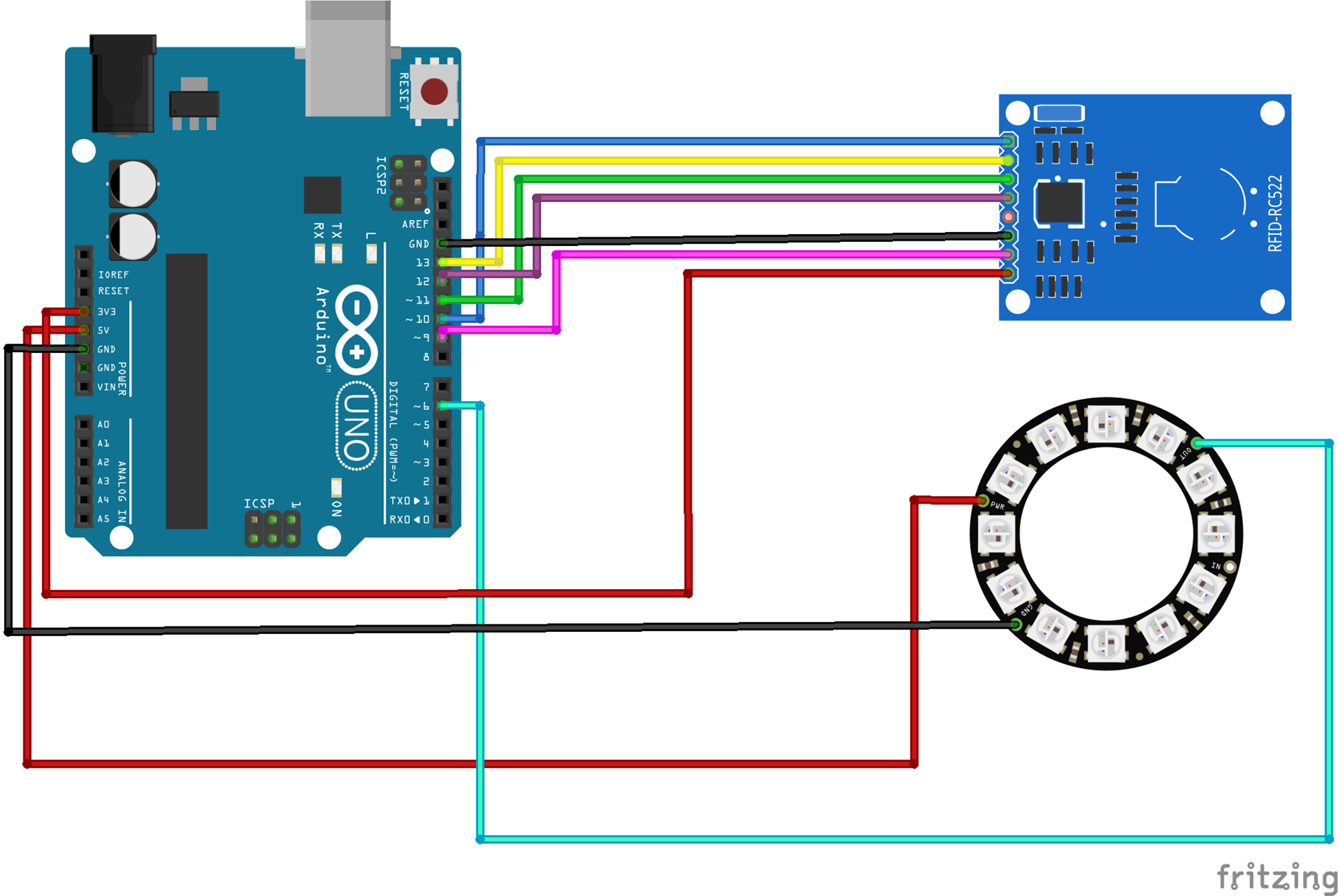
RFID Reader
- SDA → Pin 10
- SCK → Pin 13
- MOSI → Pin 11
- MISO → Pin 12
- IRQ → Not connected
- GND → GND
- RST → Pin 9
- 3.3V → 3.3V
NeoPixel Ring
- DIN → Pin 6
- VCC → 5V
- GND → GND
Serial Communication
- Used for debugging
- JSON output sent to Escape Room server
The Code
1Include Required Libraries
First, we need to include all the necessary libraries for RFID reading and LED control:
// Include required libraries
#include <SPI.h>
#include <MFRC522.h>
#include <Adafruit_NeoPixel.h>
What each library does:
SPI.h: Enables communication between Arduino and the RFID reader using the SPI protocol. SPI is a synchronous serial communication protocol that uses 4 wires (MISO, MOSI, SCK, SS) for high-speed data transfer between microcontrollers and peripheral devices.
MFRC522.h: Provides functions to interact with the MFRC522 RFID reader chip. This handles the radio frequency communication protocols needed to read 13.56 MHz RFID cards.
Adafruit_NeoPixel.h: Controls WS2812B (NeoPixel) LEDs, which are individually addressable RGB LEDs that can be chained together and controlled with a single data pin.
2Define Variables and Constants
Set up the configuration for your specific hardware setup:
// PUZZLE variables
int SOLVED = 0;

// RFID variables
String CARD_ID = "5A 49 8E AB"; // Your valid card ID
const int RST_PIN = 9;
const int SS_PIN = 10;
MFRC522 mfrc522(SS_PIN, RST_PIN); // Create MFRC522 instance

// LED ring variables
const int LED_PIN = 6;
const int LED_COUNT = 12;
int thisLED = 0;
int nextLED = 0;
int nextnextLED = 0;
int PATTERN = 1; // 1=start, 2=success, 3=invalid, 0=solved
Adafruit_NeoPixel ring(LED_COUNT, LED_PIN, NEO_GRB + NEO_KHZ800);
What each variable does:
SOLVED: Acts as a boolean flag to prevent multiple successful reads after the puzzle is completed.
CARD_ID: The hexadecimal UID (Unique Identifier) of the authorized RFID card. Each RFID card has a unique 4-byte identifier burned into it during manufacturing.
RST_PIN/SS_PIN: Hardware control pins. RST resets the RFID module, SS (Slave Select) tells the module when the Arduino wants to communicate.
MFRC522 object: Creates an instance of the RFID reader controller with specified pins.
LED animation variables: Track positions for creating a smooth "comet tail" effect during scanning.
PATTERN states:
1 = Scanning mode (red spinner)
2 = Success animation (green cascade)
3 = Invalid card (red flash)
0 = Solved/idle state
Ring object: Initializes NeoPixel controller with color order (GRB) and communication frequency (800KHz).
3Setup Function
Initialize all components in the setup function:
void setup() {
    SPI.begin();           // Initialize SPI bus
    mfrc522.PCD_Init();   // Initialize MFRC522 reader

    ring.begin();         // Initialize LED ring
    ring.show();
    ring.setBrightness(200);

    Serial.begin(9600);   // Initialize serial communication
}
What each line accomplishes:
SPI.begin(): Configures pins 11 (MOSI), 12 (MISO), and 13 (SCK) for SPI communication. Sets the Arduino as SPI master device.
mfrc522.PCD_Init(): Performs soft reset of RFID module, configures antenna gain, and sets up communication parameters for 13.56 MHz cards.
ring.begin(): Allocates memory for LED color data and configures the data pin for output.
ring.show(): Sends the current color data to the physical LEDs. Initially all zeros, so LEDs turn off.
ring.setBrightness(): Scales all color values globally (useful for power management and preventing eye strain).
Serial.begin(): Opens UART communication for debugging and JSON output to escape room control system.
4Main Loop - Card Detection
The main loop continuously checks for RFID cards and validates them:
void loop() {
    // Check if a new card is present
    if (!mfrc522.PICC_IsNewCardPresent()) {
        // Continue scanning animation
    }

    // Read the card if not already solved
    if (!mfrc522.PICC_ReadCardSerial() && SOLVED == 0) {
        PATTERN = 1; // Keep scanning pattern
    }
    else if (SOLVED != 1) {
        // Convert card UID to string
        String tagString = "";
        for (byte i = 0; i < mfrc522.uid.size; i++) {
            tagString.concat(String(mfrc522.uid.uidByte[i] < 0x10 ? " 0" : " "));
            tagString.concat(String(mfrc522.uid.uidByte[i], HEX));
        }
        tagString.toUpperCase();

        // Check if card is valid
        if (tagString.substring(1) == CARD_ID) {
            Serial.println("{\"shortName\":\"SOP\",\"type\":\"SOLVE\",\"solved\":true}");
            PATTERN = 2; // Success pattern
            SOLVED = 1;
        } else {
            PATTERN = 3; // Error pattern
        }
    }

    // Handle LED patterns...
}
Breakdown of the code:
PICC_IsNewCardPresent(): Sends radio frequency pulses to detect if any RFID card is within range (~5cm). Returns false if no card detected, allowing animation to continue.
PICC_ReadCardSerial(): Attempts to read the UID from detected card. This involves:
Sending authentication request
Reading card's response
Storing UID in mfrc522.uid structure
UID to String conversion:
Iterates through each byte of the UID (usually 4 bytes)
Adds leading zero for single-digit hex values (0x09 becomes "09")
Converts to hexadecimal string representation
The ternary operator ? : adds " 0" if value < 0x10, otherwise just " "
substring(1): Removes the first space character added during concatenation.
JSON output: Formatted for integration with escape room server using standard JSON structure.
5LED Pattern Animations
Create different visual feedback patterns for each state:
Scanning Pattern (Red Spinner)
if (PATTERN == 1) {
    // Calculate LED positions for trailing effect
    nextLED = thisLED - 1;
    nextnextLED = thisLED - 2;

    // Handle wraparound
    if (thisLED == ring.numPixels()) {
        thisLED = 0;
        nextLED = 11;
        nextnextLED = 10;
    }

    // Clear all LEDs
    ring.fill(0, 0, 12);
    ring.show();

    // Set main LED (brightest)
    ring.setBrightness(250);
    ring.setPixelColor(thisLED, 200, 0, 0);

    // Set trailing LEDs (dimmer)
    ring.setBrightness(150);
    ring.setPixelColor(nextLED, 200, 0, 0);

    ring.setBrightness(25);
    ring.setPixelColor(nextnextLED, 200, 0, 0);

    ring.show();
    thisLED++;
    delay(80);
}
Animation breakdown:
Creates a "comet" effect with three LEDs of decreasing brightness.
Wraparound logic ensures smooth circular motion (when lead LED goes past 11, it wraps to 0).
The brightness gradient (250→150→25) creates the illusion of motion blur.
80ms delay creates ~12.5 FPS animation.
Success Pattern (Green Cascade)
else if (PATTERN == 2) {
    // Clear ring
    ring.fill(0, 0, 12);
    ring.show();
    delay(125);

    // Cascade effect
    for (int i = ring.numPixels() - 1; i >= 0; i--) {
        ring.setPixelColor(i, 0, 200, 0);
        ring.show();
        delay(50);
    }

    // Flash sequence
    for (int flash = 0; flash < 3; flash++) {
        ring.fill(ring.Color(0, 255, 0), 0, 12);
        ring.show();
        delay(500);
        ring.fill(0, 0, 12);
        ring.show();
        delay(500);
    }

    PATTERN = 0; // Turn off lights
}
Animation breakdown:
Initial clear provides visual separation from scanning mode.
Cascade fills LEDs one by one from position 11 to 0 (counterclockwise).
Triple flash provides success feedback.
Total animation time: ~4.7 seconds (125ms + 600ms cascade + 3000ms flashing).
Error Pattern (Red Flash)
else if (PATTERN == 3) {
    // Flash all LEDs red
    ring.fill(ring.Color(255, 0, 0), 0, 12);
    ring.show();
    delay(2000);
    PATTERN = 1; // Return to scanning
}
Animation breakdown:
Immediate full-ring red flash indicates unauthorized access attempt.
2-second duration ensures user sees the rejection.
Automatic return to scanning mode for retry.
Testing Your Security Panel
1Finding Your Card's UID
To find the UID of your RFID card, upload this test sketch:
void loop() {
    if (mfrc522.PICC_IsNewCardPresent() && mfrc522.PICC_ReadCardSerial()) {
        Serial.print("Card UID: ");
        for (byte i = 0; i < mfrc522.uid.size; i++) {
            Serial.print(mfrc522.uid.uidByte[i] < 0x10 ? " 0" : " ");
            Serial.print(mfrc522.uid.uidByte[i], HEX);
        }
        Serial.println();
    }
}
What the test code does:
Combines card detection and reading in single if statement for efficiency.
Prints UID in same format expected by main code.
Essential first step - you must know your card's UID before configuring the system.
2Troubleshooting Common Issues
RFID Reader Not Working
- Check SPI connections (especially MISO/MOSI)
- Verify 3.3V power (not 5V!)
- Ensure RST pin is connected
- Try a different RFID card
LEDs Not Lighting
- Check data pin connection (Pin 6)
- Verify 5V power supply
- Test with simple blink sketch
- Check LED count matches your ring
3Integration with Escape Room System
The code outputs JSON format which is sent to the Escape Room server.
{
    "shortName": "SOP",
    "type": "SOLVE",
    "solved": true
}
This JSON is parsed by a Node-RED server and triggers the launch of the shuttlecraft from the Nebula Dawn.
Possible Enhancements
Multiple Valid Cards
Store an array of valid UIDs to allow different access levels or team-based puzzles.
Sound Effects
Add a buzzer or speaker module for audio feedback on success/failure.
Network Integration
Use an ESP32 instead of Arduino Uno to add WiFi capabilities for remote monitoring.
Get in touch!
We are currently looking for educators and students to collaborate with on future projects.
Get in Touch!
hello@escapehumber.ca